Your Cart is Empty

We get a lot of technical inquiries about BorgWarner EFR installations as the turbochargers are quite different in many ways from your typical aftermarket performance turbochargers. This guide will help cover the basics about the Turblown Cast EFR IWG Rx7 Turbo system & other installs as well. Our Rx7 specific install video can be found here; Turblown Cast EFR IWG Turbo System Installation Video
Internally Wastegated configuration setup & installation
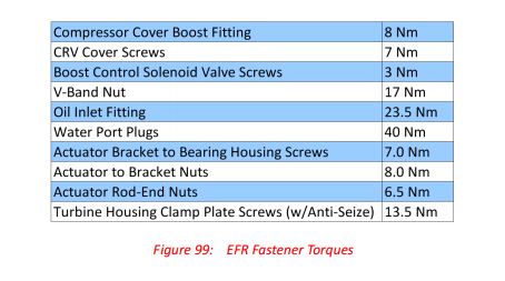
The wastegate rod thread is M6 x 1.0 which means that each full turn of the nut equals a 1mm change in extension. By tightening the nut one turn at a time, a known preload (1mm) can be applied to the rod and canister spring. As preload is added, the spring inside the canister compresses and exerts more force to hold the wastegate flap closed. The downside of added preload is loss of stroke. In other words, the rod travel that is consumed by preload setting is no longer available for rod stroke motion (during use). The valve will not be able to open as far, so maximum wastegate valve flow will be limited.
Wastegate behavior is tuned in two ways. First, the wastegate canister is selected. Second, the rod preload is set. There are three canisters offered, simply called “low boost”, “medium boost”, and “high boost”. 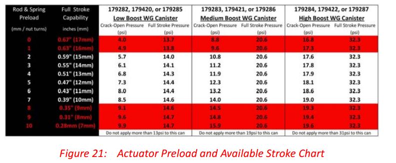 As you would expect, the “low boost” actuator requires a low pressure to be applied before cracking the wastegate open. It is also sprung quite softly, so as canister applied pressure increases, the amount of rod movement increases quickly. This actuator is meant for vehicles running low boost pressures (less than 10psi) or vehicles running medium boost (10-15psi) that have an electronically-controlled spill valve (e.g BCSV) on the actuator line. The “medium” boost actuator is the default on EFR turbos and is targeted at the user running 12-18psi boost pressure straight off the supply hose or with mild amounts of electronic spill control. The “high” boost actuator is quite stiffly sprung and is reserved for those running 20-30psi boost (or higher, when using spill).
Avoid twisting the rod while tightening the adjustment nuts. Hold the rod steady while turning the nuts. The rod threads are 1mm pitch, so each turn of the nut equals a 1mm change in preload. We recommend at least 2mm of preload applied to the rod, preferably 4mm for rotary engines running no less than 13psi. This applies force to keep the wastegate valve held closed, and also prevents premature vibration wear of the canister internals.
If one is looking to run both a low, and very high boost setting a Turbosmart dual port IWG actuator should be considered. The OE EFR unit is only a single port unit, with 3 fixed spring pressures. The Turbosmart models offer a wide range of base springs, and a secondary boost pressure source on the backside of the diaphragm. Applying boost pressure to the bottom side of the IWG actuator helps keep the WG valve closed for high boost settings and conditions of high exhaust manifold back pressure. The unit will yield the ultimate in IWG performance. The new genV IWG actuator with wg position sensor installed below. This allows you to datalog the WG position to help better dial in your boost control, and trouble shoot etc.

BCSV(Boost Control Solenoid Valve) installation & notes
 The best boost control is achieved by using an electronic spill valve such as the unit built into the EFR compressor cover. This valve “vents” pressure from the wastegate canister’s signal port. The net effect is that the canister can have a non-linear response to applied pressure and a more precise opening point and opening rate. Most of the time one can achieve a lower boost threshold with a boost controller over using spring pressure alone.
The solenoid valve uses an “injector type” connector, and the BSCV connector itself is marked with a polarity symbol. There are two connections, +12V and ground. The valve is pulsewidth controlled and the wave frequency should be less than or equal to 32 Hz. The resistance of the BCSV coil is 23 Ohms.
Water Cooled Bearing Housing installation guide
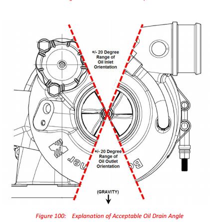
The bearing housing castings are water-cooled, and four M14x1.5 ports are provided. Two plugs are also provided so that the ports not being used can be capped off. It does not matter which side of the bearing housing gets the inlet flow and which side gets the outlet flow, but the flow must be diagonal across the housing . Also, the inlet port needs to be on the bottom and the outlet port needs to be on the top. This is to encourage evacuation of air bubbles as well as to encourage auto-siphoning (flow movement through natural convection) during the shut down’s heat soak. Water cooled ports should always be used if possible, but not required on all applications. Rotary engines, time attack, autoX or roadcourse driven cars should always use the water ports. If the EFR being installed uses the Aluminum bearing housing, the water cooled ports must be used for longevity.
CRV(compressor recirculation valve), aka recirc bov installation and notes
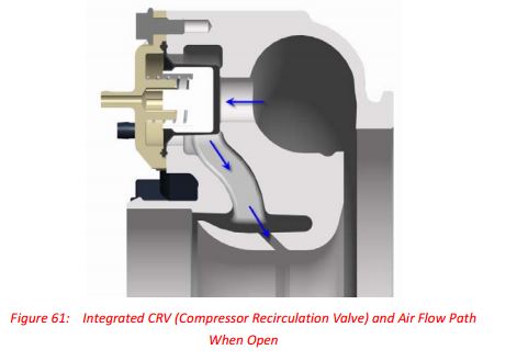 Recirculating the flow back into the compressor inlet helps keep MAF engine management systems “happy” and also helps keep turbo speeds high during the shift. When upgrading the CRV to a Turbosmart unit we generally prefer to use the plumb back version over the dual port for the above reason. We only recommend the dual port unit, when increase venting is required( 28+ psi).
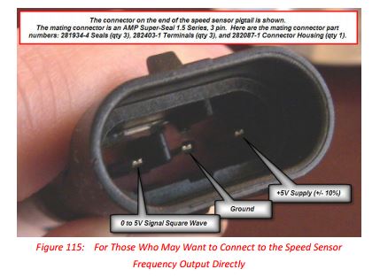
Shaft Speed Sensor Installation
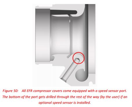 If a user decides to buy a speed sensor as an upgrade accessory, they can remove the compressor cover and extend the hole the rest of the way through to the wheel bore using a hand drill. A shaft speed sensor should be installed if one is trying to maximize the performance of the turbocharger, especially the larger turbine units. Shaft speeds on the EFR 9180 & EFR 9280 should not exceed 115,000RPMS for longevity of the turbine wheel.
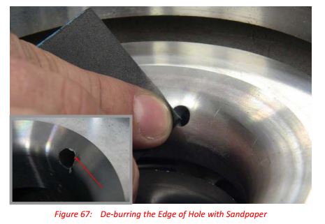
 A 1/4” drill bit is used and the length required to be drilled is quite short. This hole allows the tip of the sensor to come flush with the contour surface. The hole does not have to be precise, as no sealing takes place in the small hole that the user just created. The hole should be de-burred where it pierces into the wheel bore. The goal is to make sure that there are no sharp edges remaining in the wheel bore that the compressor can become snagged on. Installation steps:
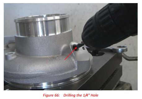
 Remove compressor cover from turbo (CAREFULLY) 2. Place cover on a table, with some kind of backing so that it won’t slide while being drilled 3. Equip a hand drill with a 1/4” drill bit 4. Drill out the bottom of the speed sensor bore while being careful not to nick the side-walls
 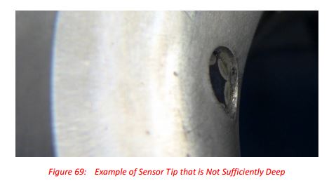 of the bore where the speed sensor o-ring will seal. 5. De-burr the hole where it protruded into the compressor wheel region. 6. Lubricate the speed sensor o-ring 7. Install the speed sensor into the bore and check for a good fit. 8. Use a file on the mounting surface if the sensor needs to protrude further into the bore. The sensor tip should be nearly flush (within 0.5mm) with the edge of the hole. 9. Tighten speed sensor hold-down bolt. 10. Re-install compressor cover on turbo and verify that the compressor wheel spins freely.
Oil Feed installation
 Additional oil restrictions should not be used. The required restriction to throttle the oil flow to the ball bearings is already integrated into the bearing housing. The oil supply line should be kept as short as possible. If a line of unusual length is required, we recommend a -6AN line especially for very cold climates. -3AN line is not recommended due to excessive oil supply delay times during cold start. We recommend that oil reaches the turbo in less that 4 seconds during a cold start cranking, and in under 1 second during hot-start conditions. We often get questions about oil selection. The simplest answer is that turbos prefer warm (but not overly hot), high viscosity (e.g. 10W40), synthetic oil. Non-synthetic oils may of course be used but the user can expect a higher degree of laquering and coking. Users of thin oil (e.g. 5W20) can expect lesser bearing system robustness against harsh conditions or abuse, especially if the oil is very hot. Inlet oil pressure (gage) is recommended to be at least 1bar (15psi) and not more than 4bar (60psi) under all “fully warmed-up” conditions. We have yet to see a smoking problem from running oil pressures above 60 psi when warm, like on rotary engines.
Misc Installation notes & original content credits
Comments will be approved before showing up.