Your Cart is Empty

New for 2018 Turblown Engineering improves their twinscroll FD3S Rx7 turbo manifold drastically by casting it. The current design was developed back in 2013, after 13 years of testing 20+ designs. These designs ranged from low mount, high mount, bottom mount, different lengths, tubing sizes, flanges(vband, T4 open/divided etc) ,waste-gate merge angles etc. T4 flange placement over the years did not change much for the long runner design as its position is optimized to fit the vast majority of turbos, inter-cooler kits, idler pulleys, intake manifolds, and RHD steering racks etc.
The biggest change back in 2013 was the waste-gate placement & number of waste-gates. The new twin waste-gate, fully divided (twin-scroll) design separated the pulses between rotors, which increased power and reduced turbo lag. It increased power because the rotors were no longer allowed to cross communicate. There is a point in the exhaust stroke where one rotor is experiencing a high exhaust back pressure pulse, and the other rotor is at a lower pressure pulse. The higher exhaust back pressure pulse will move into the lower pressure rotor’s chamber on a turbo manifold that is not fully divided. This cross communication increases the amount of exhaust dilution into the following intake stroke, which decrease fresh cylinder fill in the next intake stroke. This decreases VE, and power. One can read more in depth converge including a back to back dyno test here by Dsport Magazine. . Full Race also had a very nice article about twinscroll vs single scroll turbo systems including in depth technical analysis. These articles are about piston engines, but the exact same concept applies to the rotary engine.
Exhaust velocity slows down on a single waste-gate turbo manifold when the high pressure pulse comes out one main runner, flows into the waste-gate runner, and then flows up the other rotors waste-gate runner/main runner, and rotor chamber( on one of the low pressure pulses). Any time there is a sudden increase in volume in an exhaust system, this decreases velocity. A decrease in velocity adds lag. Here is a quote from Borgwaner's EFR technical bulletin;
Twin-scroll housings are becoming very popular for performance use, and for good reason. By dividing the manifold and turbine housing into two flow paths, the engine firing order can be made to “alternate” the flow all the way to the turbine wheel inlet. The engine blow-down pulse is generated when the exhaust valve opens. During the blow-down, the engine power cylinder is still at very high pressure as a residual of combustion and the power stroke. This initial “pop” of energy travels at very high speed down the manifold runner, through the volute, and impacts the wheel. For this reason, the stream is very much a “pulsed flow” and the divided nature of the system simply amplifies and arranges those pulses. The obvious result is quicker spool and better low-end boost response.
Here you can see the older welded manifold that the new cast version came from. This unit is now discontinued.


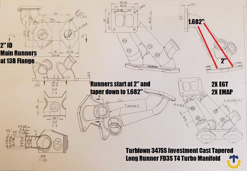
After the first stage of revisions, you can now see the main runner inside diameter was changed and a long gradual taper added. Previously the welded manifold was made from schedule 10 1.5" pipe which has an inside diameter of 1.682". The next size up in schedule 10 pipe is 2", which has an inside diameter of 2.157". We have previous found that using this size pipe is just too large for 99% of applications. We built two identical cars with one being 2" schedule 10 pipe, and one 1.5" schedule 10 pipe. The larger schedule 10 was much laggier, and a much smaller power band, with no gains in top end peak performance. Only a T6 frame turbo running at drag car power level( over 550+rwhp per rotor) benefits from this configuration. What you see below combines the best of both worlds to allow maximum velocity and power levels for a T4 frame turbocharger. The runners start off at 2" ID, and taper down gradually to 1.682". This mimics the exact same casting process found inside that of a turbine housing. Also notice 2 more 1/8NPT ports are added( 2 for egt, and 2 for emap).
Now that the design revisions are complete, the first stage of the casting process is shown below. A wax mold is made.

Lost Wax Model
Once the wax model is complete, a mold is made around it. The wax model is then melted out, also known as the "burn out" process.

A raw cast unit after going through the complete investment casting process.

Final samples after being fully machined. Its rare to see any vband wastegate flanges machined into cast manifolds. If you look around you see most other manufacturers weld this portion on. We wanted the best that money could make bar none. Here are the finished samples ready for fitment & dyno testing.
Comments will be approved before showing up.